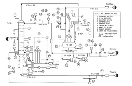
Process & Instrumentation Diagram
A Process and Instrumentation Diagram (P&ID) is the focal drawing in all process plants. P&ID is a type of engineering drawing that describes all the process steps of a plant. It basically is a process plant on a paper. It is a schematic diagram of pipes, process equipment, and control systems by a set of pre-decided symbols with no scale and no geographical orientation. It provides a lot of information for the manufacturing of the equipment, installation, commissioning, startup, and the operation of a plant. It also presents how a process plant should handle emergency situations.
Usefulness of P&IDs
The P&ID is a frequently referenced document throughout a project term – from the designing stages to the plant‐in‐operation phase – by various engineering disciplines, in technical meetings with vendors or manufacturers, hazard and operability study (HAZOP) meetings, management meetings, and project scheduling and planning. It is also one of the few documents created by multiple engineering groups such as process, instrumentation and control, piping, mechanical, structural, and environmental or regulatory groups.
Furthermore, P&IDs are crucial in facilitating the designing of:
- Schemes for control and shutdown.
- Requirements for safety and regulation.
- Sequences for start-up.
- Operational details and understanding.
Structure of a P&ID

There is no ideal standard concerning the structure of P&IDs. A group of process industry owners and engineering construction contractors in the industry laid out many must-haves in a piping and instrumentation diagram in (PIC001: Piping and Instrumentation Diagram Documentation Criteria). Below is what a P&ID should entail:
- Mechanical machinery named and listed numerically.
- All valves and their identifications.
- Process piping, sizes, and identification.
- Vents, drains, special fittings, sampling lines, reducers, increasers.
- Permanent start-up, flush edges, and flow directions
- Interconnection references, control inputs, and output interlock.
- Seismic category and annunciation inputs.
- Computer control system input.
- Vendor and contractor interfaces.
- Identifications for outsourced components and subsystems.
- The estimated physical sequence of the equipment and its rating or capability.
Equipment symbols are typically a side view of the real shape of the equipment, and if possible, are shown relative to their actual sizes. Different types of lines on the P&ID represent pipes and signals. However, the lengths of the lines do not represent the real length of pipes or signal carriers (e.g., wires).


