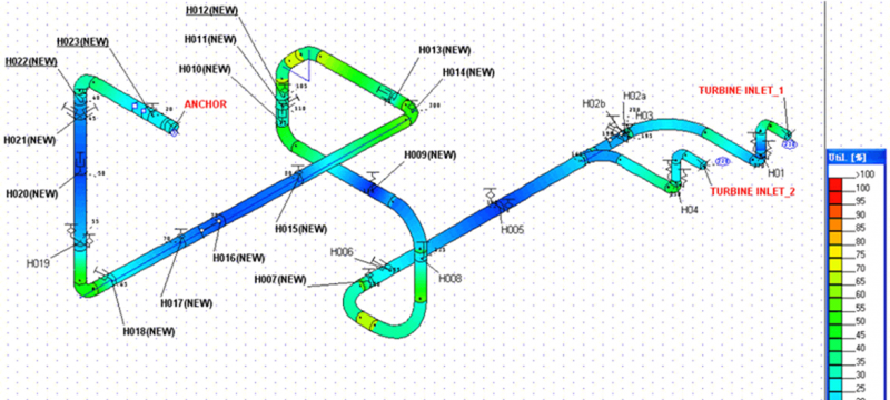
Piping Stress Analysis
Piping systems are subjected to a variety of extreme conditions of temperature and pressure.
Our piping stress engineers at Petroplat, has a proven track record in providing pipe stress analysis services using CAESAR II. Our Piping Stress Engineer has been providing in-depth technical knowledge and proven performance in the fields of Piping Stress Analysis, Piping Engineering and Pipe Support Design to Oil & Gas, Chemical Processing Plants and EPC Companies at various locations around the Globe. We know that Piping Stress Analysis is a vital part of any plant layout our Piping Engineers co-ordinate with other disciplines working on a project. Have excellent expertise in understanding your physical system and performing the stress analysis by changing them into a detailed model. We can provide you with the best piping stress analysis for industries within a short period of time.
Our Piping Stress Analysis Studies includes:
(1) Thermal and Sustained Stress Analysis of small and large diameter piping (ASME B31.3, ASME B31.4, ASME B31.8, CSA Z662.)
(2) Evaluation of loads on various types of equipment such as: Compressors, Centrifugal and Reciprocating Pumps, Towers and Pressure Vessels.
These are the steps involved in the stress analysis:
(1) Identify the potential loads that the piping system would encounter during the life of the plant.
(2) Relate loads of those masses to the stresses and strains developed. (Including Surge forces which might be calculated/found out by Surge.
(3) analysis using Pipenet software system.
(4) Get the cumulative effect of the potential loads within the system.
(5) Decide the allowable limits the system will withstand without failure.
(6) After the system is intended, to ensure that the stresses are within the safe limits.
Software: CAESAR II
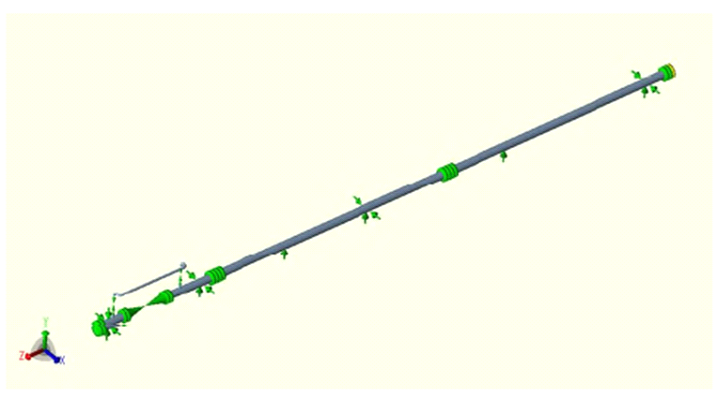
Piping Flexibility Analysis
piping flexibility study calculates the reaction loads and stresses resulting from gravity, internal and external pressure, temperature fluctuations and flow induced loads. The objectives of flexibility analysis are to calculate stress in the pipe; loads on supports, restraints, and equipment; and displacement of the pipe. It is essentially a beam analysis model on pipe centerlines. The fundamental principles include the following:
1. The analysis is based on nominal dimensions of the pipe.
2. The effect of components such as elbows and tees on piping flexibility and stress is considered by inclusion of flexibility factors and stress intensification factors.
3. For thermal stresses, only moment and torsion are typically included.
In addition, Petroplat offers below services in relation to flexibility study:
(1) Piping Flexibility analysis according to ASME B31.1/B31.3 / EN 13480
(2) Supports design (type and position)
(3) Buried pipes
(4) Check of allowable loads on nozzles (pumps, static equipment, etc.) as per WRC-107
(5) Dynamic analysis (Modal, Harmonic)
3D Modelling
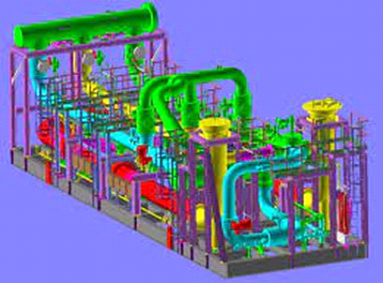
Before the complete system is physically created, 3D models of the system provide deep insights and assist in making the necessary alterations.
We translate your ideas into realistic animations, flythroughs, movies, and visualizations of any kind using modern and cutting-edge technology. Petroplat recognizes and feels that 3D images make it much easier to promote your products and design concepts. We provide you with expert designers and 3D artists to create products and presentations. We create walkthroughs, 3D visualizations based on 2D and 3D data, and various animations. Our professionals work their magic by creating 3D models from sketches, CAD drawings, images, or just verbal descriptions.
Petroplat offers 3D CAD design and fabrication services to customers in a variety of sectors and engineering fields, including manufacturing, oil and gas, civil, electrical, instrumentation, and structural designs and fabrication. We also work for both commercial and public entities on specialized industrial drawings and 3D modeling needs for Petrochemical, Pharmaceutical, Fertilizer, industries, Power, and Water Treatment Plants.
We create most of our designs in 3D CAD and 2D drawings to print on paper. Our team of designers and modelers utilize latest 3D modeling software for every project design and development from inception to implementation for fabrication/construction.
We use 2D CAD in Autodesk AutoCAD for simple Mechanical and Electrical Drawings as well as Schematics. We maintain efficiency by producing 3D models first along with changes for design and drafting.
We utilize extensive libraries and experience of textures and modeling to generate marketing collaterals and materials for your sales and marketing team along with manuals and user guides.
Our team can provide you with high-quality 3D models of your piping systems and other equipment.
Software: E3D
Client:WAEP/AVEON
Piping Material Take Off
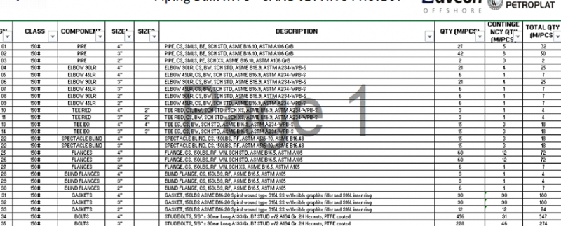
Once the design and drafting are completed, our team of piping engineers can provide you with the material take off services. This helps in the construction cost estimation process.
We offer a helping hand in your Material Take Off from the initial stage up to the final stage.
Preliminary MTO: A preliminary MTO is a material take-off very early in the design process when only a limited amount of information is known, and very little detail has been developed. A preliminary MTO is normally done for two reasons. The first is to assist with the early “order-of-magnitude” (+/- 10%) estimate for the overall project. The second reason is to issue early order of magnitude Request for Quote for piping materials.
The preliminary MTO is only possible when there is a Plot Plan that is “Approved” by the Client or has been issued to the client for approval. This is done long before the availability of any detailed 3D design model.
For the preliminary MTO we used a formatted form on which we could indicate the number or amount of material required for each line. On the form, we identify the line number along with the line class. we then look at this line on the P&ID and on the Plot Plan to determine the routing of the pipe. Then in the boxes (on the form) we mark the amount of pipe required for each size required for that line. We take count of the number of fittings required, starting with 90-degree elbows. Then continuing through all the other inline fittings and online fittings. On getting the fittings, we then, take a count of all flanges by on size basis alongside with the valves referencing the P&ID. The high point vents and low point drains would be made last based on an educated guess. This cycle will be repeated.
Secondary MTO: The primary reason for the Secondary MTO is to update quantities for the issue of the actual Purchase orders for piping material. A second reason is to update the project estimate.
The Secondary MTO can only be done when there is significant progress completed on the 3D design model (or other electronic design method). However, it must be done early enough to ensure that the procurement (purchase and delivery) of the piping material to the field will fit the overall project schedule.
Final MTO: The final MTO is done first to identify any item added late in the project or anything that was missed on the Preliminary or Secondary MTO’s. Other reason for the Final MTO is to get a fix on the final job costs. The Final MTO is done when the last Isometric has been issued.